Introduction to State
- the state is a snapshop of the system at a given moment
- state transitions take place at fixed units of time
- clock is a mechanism that triggers transition frmo one state to another in a sequential circuit
- computation needs to complete before clock cycle ends
- state-elements with clock attached (inputs evaluate, use input when clock ticks)
- pipelining (with every cycle we get more results which are the inputs to the next cycle)
A sequential circuit has a finite set of states. A synchronous sequential circuit has a clock input, whose rising edges indicate a sequence of times where state transitions occur. A circuit is synchronous sequential if
- every element is either register or combinational
- at least one register
- all elements receive the same sigmal
- every cyclic path contains min. one register
If conditions not met, then asynchronous.
The FSM
A Finite State Machine is a system that can only be in one specific condition (state) at any given time, and it changes states based on specific rules.
An FSM with registers has unique states.
A computer board needs to process information in a predictable way. FSMs are used to map out exactly how hardware should react to every possible event.
Has
-
a finite number of states
-
a finite number of inputs
-
a finite numbers of outputs
-
clock
-
optionally reset signal
-
transitions (how to get from one state to another)
-
an output function (moore or mealy)
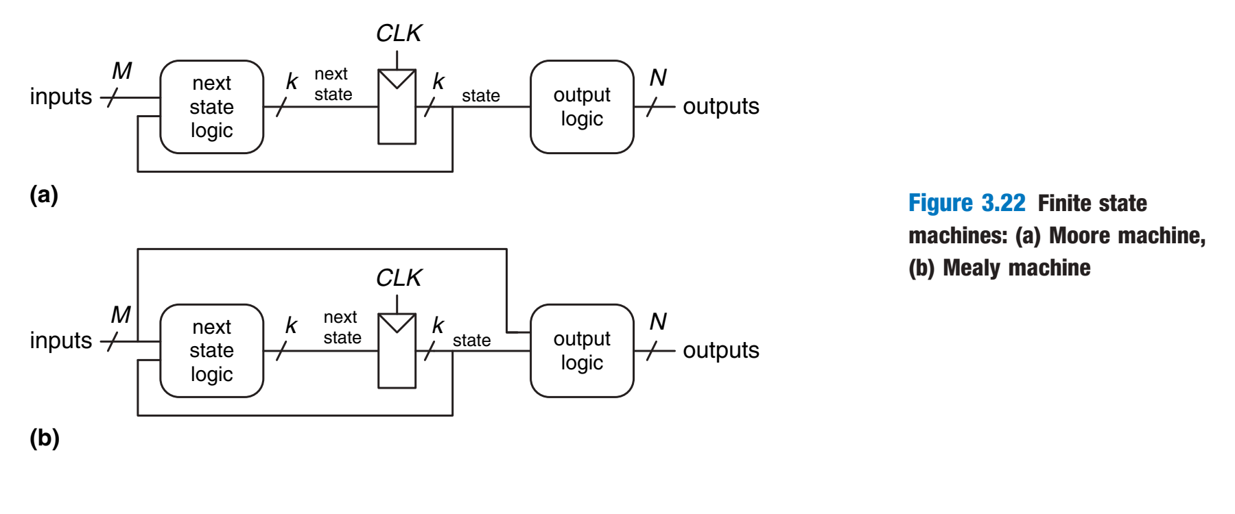
There are two types of circuits. Most system use a combination of both. Sequential vs Combinational (Combinational vs Sequential)
-
Sequential Circuits (Memory): This part uses State Registers to remember the machine’s Current State. It safely holds this information and only updates to the Next State when the system clock (CLK) ticks, keeping everything synchronized.
-
==Combinational Circuits== (Logic): Output depends only on current input, as a roolbook.
- Next state logic: Looks at the current situation and decides what the machine’s next state needs to be.
- Output logic: Triggers the actual physical actions or signals the machine needs to perform right now.
State register (CLK)
Warning
States only change at exactly the rising clock edge.
Gated D-Latch (Problems!)
Always when CLK is up, the output reflects the input. NOT WANTED
Solution: → D Flip-Flop
Moore vs Mealy
Moore FSM:
- output depends only on current state, every state has an output
- inputs cause state transitions
Mealy FSM:
- output is tied to state transition (depends on depends on current state and inputs)
Both
- don’t forget the Reset State
- all states have transitions for all inputs
FSM:
Example: 1101 Snail
Transition Diagram
Reset State
You NEED to have a reset state, this is where it starts from
Reset
Asynchronous Reset
- The reset signal is sampled independent of the clock
- Reset gets the highest priority
- Sensitive to glitches, may have metastability issues
Synchronous Reset
Link to original
- The reset signal is sampled with respect to the clock
- The reset signal should be active long enough to get sampled at the clock edge
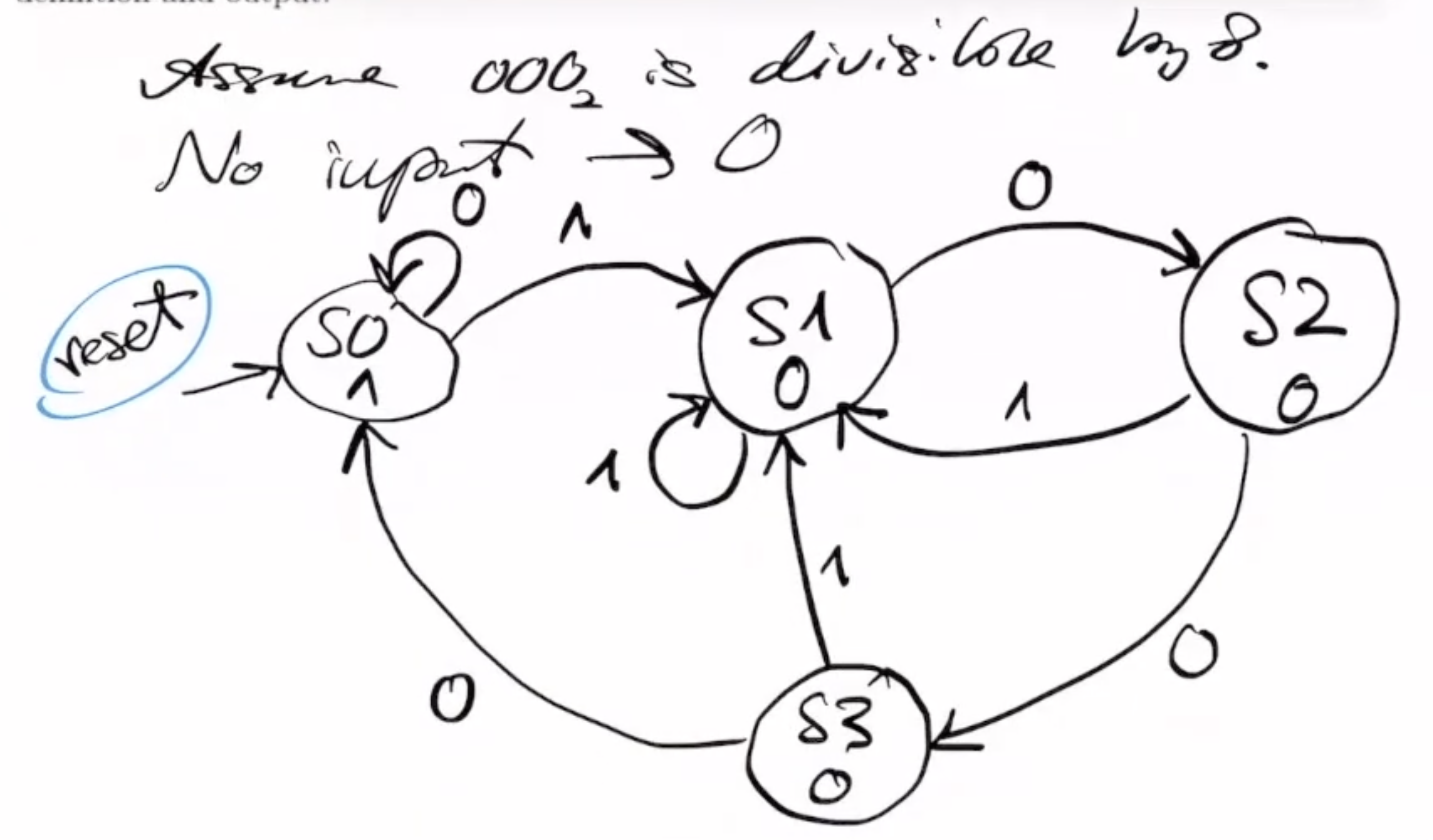
Example Task, Designing an FSM
Design a Moore FSM with one input and one output. The input provides an unsigned binary number in a bit-serial fashion from the most-significant bit to the least-significant bit. The output should be logic-1 in a clock cycle if the provided input so far is divisible by 8 (i.e., [the input number] mod 8 = 0).
Example bit-streams that should output a logic-1 value.
- 1000
- 10000
- 11000
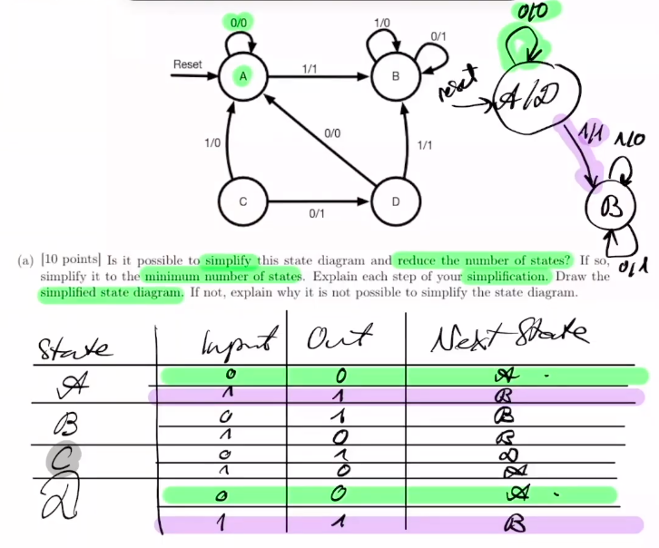
Example Task, Simplifying an FSM
- Create Table with inpout, output, next state
- Check unreachable states, f.ex. here State C, and remove
- Check identical rows, and merge
Create and check the truth table after finishing to see if it can be simplified further.