Introduction
HDL = Hardware Description Language All hardware logic operates concurrently
HDLs enable easy description of hardware structures
Wires, gates, registers, flip-flops, clock, rising/falling edge, …
Combinational and sequential logic elements
Top-Down: define the top level module and identify sub-modules all the way down to leaf cells. Leaf cells are circuit components that cannot be further divided.
Bottom-Up: define building blocks available and build bigger modules all the way up to the top-level module
The fundamental unit of design in Verilog is the
module. A module encapsulates a piece of hardware, defining its interface (inputs and outputs) and its internal structure or behavior.==Structural (Gate-Level) Approach== This approach models the circuit by explicitly instantiating basic logic gates and defining the exact wire connections between them. It acts essentially as a text-based schematic that dictates the precise physical hierarchy and layout of the hardware.
==Behavioral Approach== This method describes the circuit’s overall functionality using high-level programming constructs, such as mathematical operators and conditional statements, rather than specifying the underlying hardware.
→ using a combination of both
Basic Syntax
Gates
not my_not(output, input);
buf my_buf(output, input);

and my_and(output, input1, input2, ...);
or my_or(output, input1, input2, ...);
xor my_xor(output, input1, input2, ...);

nand my_nand(output, input1, input2, ...);
nor my_nor(output, input1, input2, ...);
xnor my_xnor(output, input1, input2, ...);
Boolean equations
Never use
assigninside of an Always block
assign y1 = a & b;       // AND
assign y2 = a | b;       // OR
assign y3 = a ^ b;       // XOR
assign y4 = ~(a & b);    // NAND
assign y5 = ~(a | b);    // NOR
Switch
must be in always statement
case (selector)
    2'b00: result = a + b;
    2'b01: result = a - b;
    2'b10: result = a & b;
    default: result = 0;
endcase
The casez statement acts like a case statement except that it also recognizes ? as don’t care.
casex (address)
    4'b1???: data_out = bus_a;
    4'b01??: data_out = bus_b;
    4'b001?: data_out = bus_c;
    default: data_out = 0;
endcase
if/else
*must be in always statement, f.ex. *
module priorityckt(input reg [3:0] a,
                   output reg [3:0] y);

  always @(*)
    if      (a[3]) y <= 4'b1000;
    else if (a[2]) y <= 4'b0100;
    else if (a[1]) y <= 4'b0010;
    else if (a[0]) y <= 4'b0001;
    else           y <= 4'b0000;
endmodule
multi input and
module and8(input  reg [7:0] a,
            output reg       y);

  assign y = &a;

  // &a is much easier to write than
  // assign y = a[7] & a[6] & a[5] & a[4] &
  //            a[3] & a[2] & a[1] & a[0];
endmodule
Modules
module example (a,b,c,y);
	input a;
	input b;
	input c;
	output y;

// circuit description

endmodule
or
module example (input a,
				input b,
				ouput y);

endmodule
Assignments
Assume we have a module small defined that takes A and B input, Y output, and we want to use that in a module top. We need to assign the inputs/outputs from small to values from top.
Syntax:
.B(C) means, the B from the module we are instanciating is connected to the C from the model that we are in.
Busses
Instead of a single wire (which can show either 0 or 1), we can use a bus (essentially a bundle of wires). To notate, we use [range_end : range_start] .
Examples:
input [31:0] a;creates an input bus nameda. It has 32 individual wires. The leftmost wire is indexed as 31, and the rightmost is 0. = 32 total bits.output [15:8] b1;declares an outputb1spanning bits 15 down to 8, so bitsinput c;means we have a single signal inputc
// You can assign partial buses
	wire [15:0] longbus;
	wire [7:0] shortbus;
	assign shortbus = longbus [12:5];
Reg vs wire
A wire represents a physical, electrical connection between hardware components. How it holds a value: It has no memory. F.ex. assign my_wire = a & b;.
A reg holds a value until you tell it to change. Must assign a value to a reg inside f.ex. an always or initial block. A reg is like memory but does NOT mean it’s an acutal register in the hardware.
Vgl. → Sequential Statements → Always
Concatenation, Copies
// Concatenating is by {}
	assign y = {a[2], a[1], a[0],a[0]);
// Possible to define multiple copies
	assign x = {a [0], a[0], a[0], a[ol}
	assign y = { 4{a[0]} }
Number Representation
Precendence of Operation
| Precedence | Operator | Description |
|---|---|---|
| Highest | ~ | NOT |
*, /, % | mult, div, mod | |
+, - | add, sub | |
<<, >> | shift | |
<<<, >>> | arithmetic shift | |
<, <=, >, >= | comparison | |
==, != | equal, not equal | |
&, ~& | AND, NAND | |
^, ~^ | XOR, XNOR | |
| ` | , ~ | |
| Lowest | ?: | ternary operator |
Structural HDL
Example, Multiplexer
Behavioural HDL
Example, Multiplexer
module mux2 (input [3:0] do, d1,
			input s,
			output [3:0] y);
	assign y = s ? d1 : d0;

endmodule
Example: 4 bit equality checker
Goal:
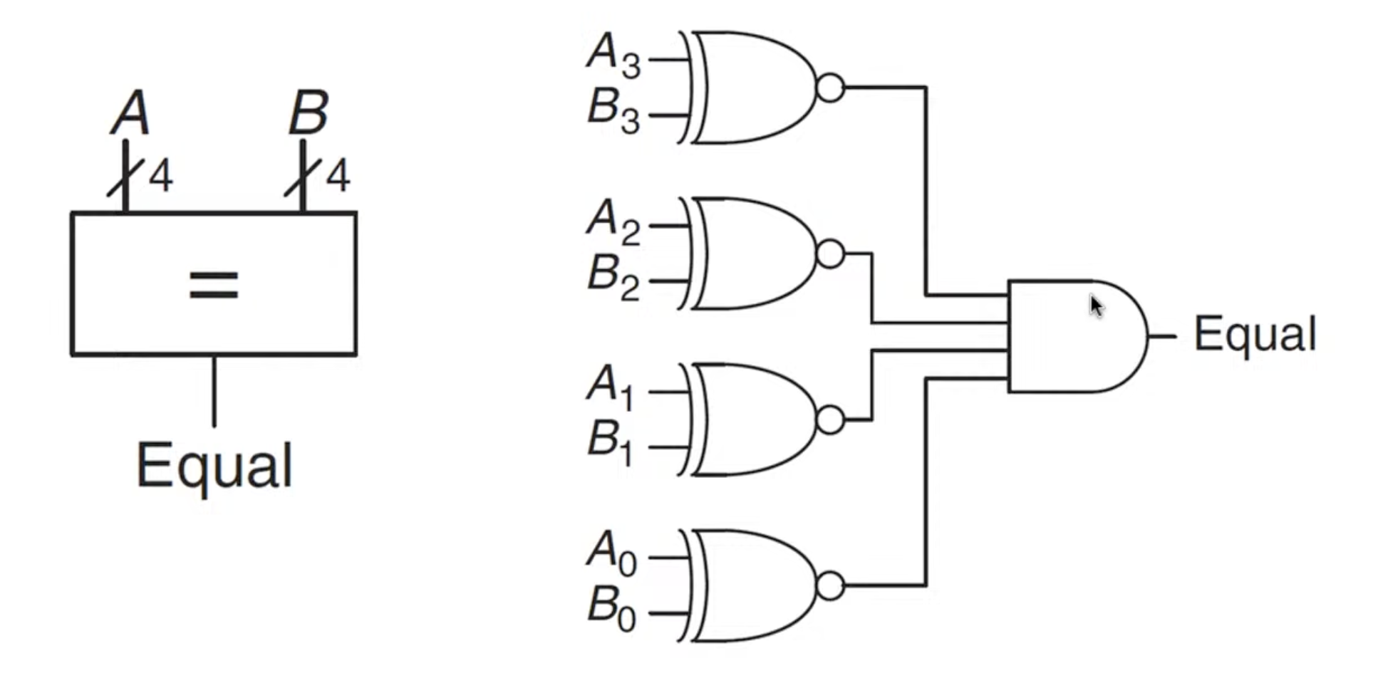
Or
Or
Or
Or
Parameters
The width parameter decides the number of inputs, the default is set to 8.
Usage:
// If the parameter is not given, the default (8) is assumed
	mux2 i mux (d0, d1, s, out);
// The same module with 12-bit bus width:
	mux2 #(12) i mux_b (d0, d1, s, out);
// A more verbose version:
	mux2 #(.width(12)) i_mux_b (.d0(dø), .d1(d1), .s(s), .out(out)) ;
Timing
Sequential Statements
- Sequential statements are within an always block
- Signals assigned within an always must be declared as reg
reg : Assigned variables need to be declared as reg. The name reg does not necessarily mean that the value is a register (It could be, but it does not have to be)
Always
Immer wenn was passiert, mach ma was.
Warning
- Any variable that is assigned a value inside an
alwaysblock MUST be declared as areg, NOT awire. See Reg vs wire- Do NOT put an
assignstatement in an always block
always @ (sensitivity list)
	statement;
Assign
You must use assign when you are outside of an always or initial block and you want to drive a signal continuously.
wire y1;
assign y1 = a & b;
Inside always blocks: If you are inside an always @(*) or always @(posedge clk) block, you simply write the variable name and the assignment operator (= or <=). Writing assign inside an always block is a syntax error.
reg y1;
always @(*) begin
    y1 = a & b;
end
Blocking vs non-Blocking Assignments
Blocking (a = b):
- Executes sequentially, one line after the other
- use for combinational logic
reg [3:0] new_count = 1;
always @* begin
	new_count = 0; // immediately
	// new_count is 0
	count = new_count;
end
Non-blocking (a ⇐ b):
- Executes concurrently. All right-hand sides are evaluated at the clock edge, and all left-hand sides are updated simultaneously at the end of the time step.
- use for sequential logic, f.ex.
reg [3:0] new_count = 1;
always @* begin
	new_count <= 0;
	// new_count is 1
	count <= new_count;
end // all assignments happen here
// count is 0, new_count = 1
Reset
Asynchronous Reset
- The reset signal is sampled independent of the clock
- Reset gets the highest priority
- Sensitive to glitches, may have metastability issues
Synchronous Reset
- The reset signal is sampled with respect to the clock
- The reset signal should be active long enough to get sampled at the clock edge
D Flip-Flop
- posedge: clock signal goes from 0 to 1
q <= d: the value d is copied to q
Example: FSM to adapt clock cycle
1: Definitions
module divideby3FSM (input clk,
					input reset,
					output y);  // created module

	// creates 2 memory items (registers) with each 2 bits
	reg [1:0] state, nextstate;

	// 2 means it is a two-bit number. 'b means the number is in binary format. 00 is the actual value
	parameter S0 = 2'b00; // parameter stands for contant variable (optional)
	parameter S1 = 2'b01;
	parameter S2 = 2'b10;
2: State register
The state register is the memory process of the FSM
	always @ (posedge clk, posedge reset)
	// always: run continuously, do clk at clocksignal up, reset at clocksignal down
		if (reset) state <= S0; // set to reset
		else state <= nextstate; // normal
3: Next State Logic
This is combinational, all options are covered, fixed rulebook
	always @ (*) // whenever the input (so anything because *) changes, this runs
		case (state)
			S0: nextstate = S1;
			S1: nextstate = S2;
			S2: nextstate = S0;
			default: nextstate = S0; // never used, just for optics
		endcase
4: Output Logic
Output only depends on state, so Moore type FSM. See Moore vs Mealy
	assign y = (state == S0);
	// assign is combinational logic, constantly re-assigns
endmodule
Example: 1101 Snail
Mealy Implementation.